Custom Servo Motor Mount Machining for Robots

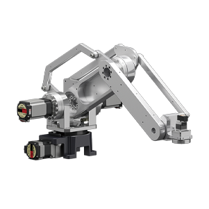
We machine each custom servo motor mount to your drawing for humanoid, quadruped and AMR robot programs.

Custom Servo Motor Mount Machining for Robots Featured Image
Overview

Servo motor mounts machined to drawing

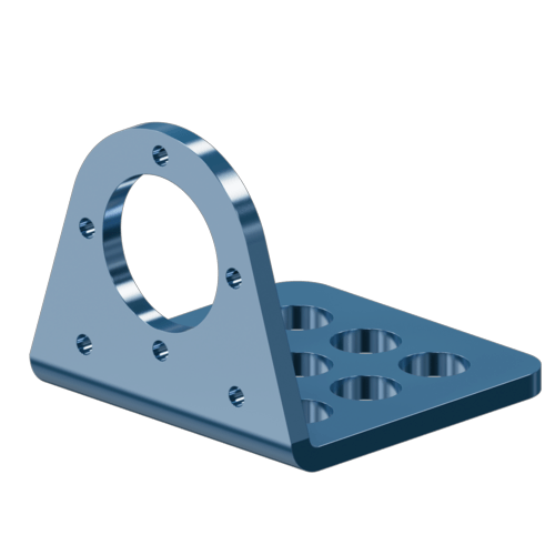
Our motor mounts keep the shaft aligned with the coupling and locate a bearing, adapt a gearbox or carry a machined heat sink. For a flat NEMA plate, buy a catalog bracket.

  • Pilot bore fit to suit the motor spigot
  • Mounting face square to the pilot axis
  • Bolt holes positioned to the pilot
  • Laser-marked revisions, prototype to repeat batches
Request A Quote
Product Intro Image
What we machine

Integrated designs we machine

  • Gearbox adapter
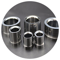
  • Bearing seat
  • Coupling housing
  • Drive-unit mount
  • Adapter plate
  • Mount and gearbox adapter
  • Mount and bearing seat
  • Mount and coupling housing
  • Drive-unit motor mounts
  • Adapter plates
  • Mount and gearbox adapter

    The motor pilot on one face and the gearbox input on the other, coaxial in one part, machined to the same datums as the robot gearbox components.

  • Mount and bearing seat

    The motor face and a bearing seat for the output shaft are machined in one setup, so the motor and the driven shaft are located in a single part.

  • Mount and coupling housing

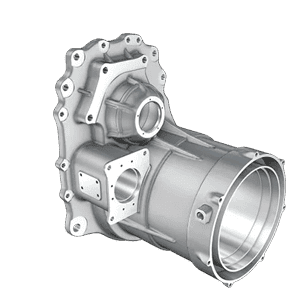
    A bell housing that carries the motor on one end and encloses the motor coupling between motor and load, with the pilot and mounting face held to your drawing.

  • Drive-unit motor mounts

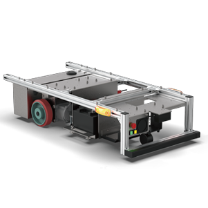
    Motor mounts for the drive units of wheeled robots, machined together with the other AGV and AMR parts of the same robot.

  • Adapter plates

    Plates for fitting a different motor to an existing interface, with the pilot bore, bolt circle and face of the new motor located to the existing mounting points.

Tech Specs

Technical Specifications

Product Specs Image
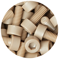
Material 6061-T6, 7075-T6 aluminum; stainless steel; POM, PEEK spacers
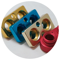
Surface finish Black (Type II) or hard (Type III) anodizing per MIL-A-8625
Masking Motor faces, grounding points masked (heat, conductivity)
Steel mount finish Black oxide or electroless nickel on steel mounts
Tolerances Pilot fit per ISO 286; hole position per ASME Y14.5; as drawn
Marking Laser marking of part and revision IDs
Application Humanoid, quadruped and AMR robot programs
Highlights

Design points by motor type

  • Servo flange location Featured Image

    Servo flange location

    The pilot centers the motor and the bolt circle clamps the flange; flange dimensions come from your motor datasheet.

  • Stepper motor mount Featured Image

    Stepper motor mount

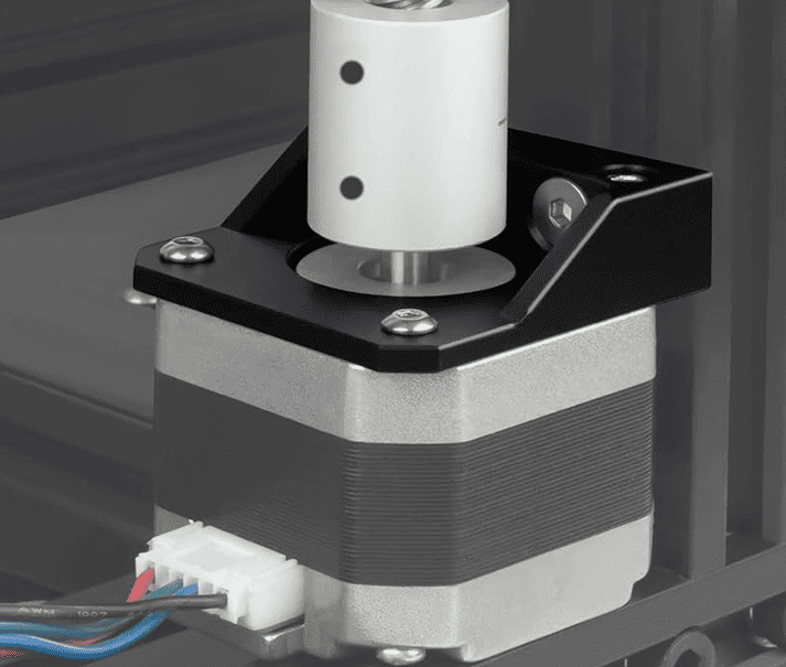
    A custom one pays off when it joins a linear-axis plate, slots for belt tensioning, a bearing block or pockets that cut moving mass.

  • Brushless motor mount Featured Image

    Brushless motor mount

    Outrunners bolt by the stator base with radial clearance around the can; inrunners use a flange; frameless stators sit in a bore.

  • Mount as heat spreader Featured Image

    Mount as heat spreader

    An aluminum mount spreads heat when its contact face is flat, masked from anodizing and large enough; fins can be machined in.

Engineering

Servo motor mount: what the geometry must control

FeatureWhy it mattersHow it is specified and inspected
Pilot boreCenters the motor on the mountISO 286 fit to suit the motor spigot, per the motor maker (e.g. H7 bore on a j6 or h6 spigot)
Bolt circle (PCD)Clamps the flange without shifting the pilotPosition tolerance of the holes to the pilot (ASME Y14.5)
Face squarenessKeeps the shaft parallel to the driven axisPerpendicularity of the mounting face to the pilot axis
FlatnessEven clamping, good thermal contactFlatness on the motor face and the base
StiffnessResists torque reaction without deflectingSection, ribs and bolt layout reviewed at DFM
Composition

Component Material & Finish

FAQs

Servo motor mount FAQs

Send your CAD model, drawing and motor model; an engineer reviews manufacturability before quoting. NDA on request.

Should I buy a catalog NEMA bracket or a custom stepper motor mount?
A catalog bracket is fine for standard frames with no space or weight constraint. A custom mount pays off when it also locates bearings, gearboxes or sensors, or must be lighter and stiffer.
What tolerances matter most on a servo motor mount?
The pilot bore fit, the perpendicularity of the mounting face to the bore axis and the bolt-hole positions. They set shaft alignment with the coupling or gearbox.
Can a motor mount act as a heat sink?
Yes. An aluminum mount with a masked, flat contact face and enough section spreads motor heat; fins can be machined in.
Which material is best for brushless motor mounts?
6061-T6 aluminum for most robots (heat and weight); 7075-T6 when thin sections must stay stiff.
Do you machine one-off prototype mounts?
Yes, with no minimum quantity for prototypes, then pilot and low-volume repeat batches with the same inspection plan.
What do you need for a quote?
A CAD model, a drawing with the motor model or flange dimensions, material, finish and quantity.