Custom Actuator Housings for Robot Joint Modules

We machine each actuator housing to your drawing for robot OEMs and actuator or joint module developers.

Custom Actuator Housings for Robot Joint Modules Featured Image
Overview

What an actuator housing does

It keeps motor, reducer, encoder and brake on one axis, carries joint loads and conducts heat. We machine it for robot servo actuators in humanoid, quadruped, cobot and mobile robots.

  • Front and rear bearing bores coaxial to one axis
  • Stator bore concentric to the bearing axis
  • CMM report and material certificate on request
  • Prototype and pilot builds to low-volume repeat runs
Request A Quote
Product Intro Image
What we machine

Actuator housing types we machine

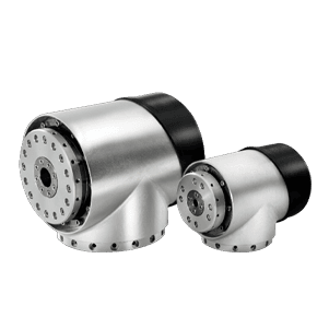
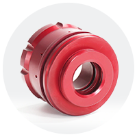
  • Rotary joint housing
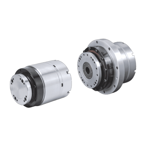
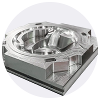
  • Strain wave housing
  • Planetary body
  • Linear actuator body
  • Joint housing, bracket
  • Rotary joint housing
  • Strain wave module housing
  • Planetary actuator body
  • Linear body and end caps
  • Joint housing and bracket
  • Rotary joint housing

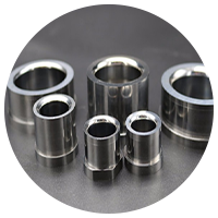
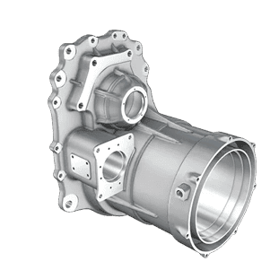
    A short cylinder with flanges for humanoid, quadruped and cobot joints. Critical features are the stator bore, the front and rear bearing seats and the reducer spigot.

  • Strain wave module housing

    A thin-walled ring around the flexspline of a strain wave joint module. The circular spline seat and the bearing seats carry the accuracy of the joint.

  • Planetary actuator body

    A body with a ring-gear seat, or an integrated ring gear machined to your drawing on request, to the accuracy grade specified on that drawing. The ring seat stays concentric to the output bearing.

  • Linear body and end caps

    Linear actuator bodies are long bores with end faces, closed by end caps. The key controls are bore straightness and the rod-end seal seats.

  • Joint housing and bracket

    Brackets, forks and clamshells that carry the actuator. Mounting faces and hole patterns are held to the same datums as the motor mounts of the module.

Tech Specs

Technical Specifications

Product Specs Image
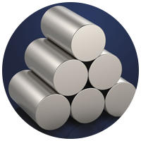
Aluminum 6061-T6 default; 7075-T6 for compact, high-torque joints
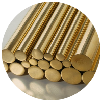
Steel, Ti, plastics 17-4PH or alloy steel inserts; Ti-6Al-4V; PEEK, POM spacers
Process CNC machined from billet on 5-axis and mill-turn machines
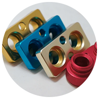
Anodizing Hard anodize MIL-A-8625 Type III; black anodize Type II
Other finishes Electroless nickel; laser-marked joint and revision IDs
Tolerances From your drawing; bearing fits per ISO 286, GD&T to ASME Y14.5
Inspection CMM on bores and positions; fit control; revision marking
Documentation CMM report, material certificate, FAI report on request
Highlights

Design points for an actuator housing

  • Coaxial bore stack Featured Image

    Coaxial bore stack

    Bearing seats, stator bore and reducer spigot share one axis, so the air gap stays even and the reducer runs true.

  • Load path through walls Featured Image

    Load path through walls

    Joint torque and tilting moments pass through the housing walls into the next link; thin walls are checked for distortion.

  • Housing as heat sink Featured Image

    Housing as heat sink

    Wall thickness, stator contact area, fins and anodize thickness set the motor temperature; anodizing also insulates.

  • Tight where it counts Featured Image

    Tight where it counts

    Tight values go on the bearing seats, stator bore and spigot, checked by CMM against your GD&T; CMM report on request.

Engineering

Critical features and tolerances

FeatureWhy it mattersTypical control (from your drawing)
Bearing seats (crossed roller, angular)Bearing life and joint stiffnessBore tolerance per the bearing maker, H6, H7, J6 or K6 (ISO 286); roundness; shoulder squareness
Coaxiality of front and rear boresReducer and motor run trueCoaxiality to ASME Y14.5 or ISO 1101
Stator boreUniform air gap for a bonded or press-fit frameless statorFit for the stator, concentric to the bearing axis
Reducer spigot and bolt patternReducer alignment and torque transfer (see robot gearbox components)Position tolerance on the bolt circle, spigot fit
Sealing faces and O-ring groovesDust and moisture protectionRa and groove dimensions per the seal maker; IP class per IEC 60529 (IP54, IP65, IP67)
Thin wallsWeight of a compact jointWall thickness checked against distortion during roughing and finishing
Composition

Component Material & Finish

FAQs

Actuator housing FAQs

Send CAD and drawing with material, quantity and datums; an engineer reviews DFM before quoting. NDA on request.

What is the purpose of an actuator housing?
It aligns the motor, reducer, bearings and encoder, carries the joint loads and conducts motor heat away. It also seals the actuator from dust and moisture.
Do you sell complete robot actuators?
No. We machine the housings and related parts to your drawing; you or your actuator supplier assemble the module.
How do you keep bearing bores coaxial?
By machining both bores in the same setup on 5-axis or mill-turn machines where the geometry allows, then checking coaxiality on a CMM.
Aluminum or steel for an actuator housing?
Aluminum (6061-T6 or 7075-T6) is the default for weight and heat transfer; steel inserts or 17-4PH are used where threads or bearing seats wear.
Can you anodize without affecting bearing fits?
Yes: bores and grounding faces are masked or machined after anodizing, as specified on your drawing.
What is the minimum order?
No minimum for prototype orders; production batches are quoted per part.